By David Bry
Technicians in independent shops working on many different brands can save time on diagnostic procedures by looking for common ground in typical systems, and then using “tricks of the trade” that apply to most vehicles. In many cases, by looking at the wiring diagram, developing an understanding of how the circuit works, and doing a few simple tests, you will determine the source of the fault. Ultimately, your task is to determine if the problem is related to a primary ECU, the wiring, or the sensor itself.
Here we are going to look at some sensor circuits, learn how they work, and then apply that knowledge to a simple testing of the circuit. Our intent is that you will pick up test procedures that will make your testing faster and more accurate. Armed with this knowledge, you can dive into a typical sensor circuit and be able to test it efficiently.
Before you start you may need to look at your tool collection to see if you have the proper equipment to test electrical systems on today’s vehicles.
—Digital Volt Ohm Meter (DVOM): Proper testing requires an accurate DVOM. This is not the time to “cheap out.” Expect to pay over $140 for a quality DVOM. Buy a case to protect it, and don’t let the guy in the stall next to you borrow it. “Smart” probes are not a substitute for an accurate DVOM in the hands of a well-trained technician.
—Testing probes: You’ll need some back-probe adapters. They’re an excellent alternative to piercing insulation to test wiring which lets moisture and dirt in leading to future failures. Some jumper leads also come in handy. The 10-inch variety is sufficient for most automotive applications. A “low-amp” amp probe will be useful for measuring current flow without tapping into wiring. When coupled with a “Fuse-Buddy” current loop you will be able to determine if the current flow of a component is in excess of design parameters. Later, when you obtain a Digital Storage Oscilloscope (DSO), the amp probe will be valuable for testing injectors on direct-injection engines, monitoring duty cycle on components such as fuel pumps, and testing variable valve timing operation and cam/crank correlation.
—Infrared thermometer: Once you have one, you’ll wonder how you functioned without one. Do you have a relay that you suspect has worn, pitted contacts? Check its temperature. If it is badly worn it usually will be warmer when operating than another relay substituted in the same location over the same amount of time. Is the temperature sensor reporting temperatures that don’t seem correct? Verify sensor temperatures by scanning the base of the sensor with your infrared thermometer.
—Scan tool: Lastly, you will need a scan tool that can display comprehensive data lists at a minimum and, preferably, full bidirectional functional testing.
When you have developed proficiency in using these testing tools, start looking at infrared cameras and color borescopes. But, for now, the above items will suffice.
Testing an engine coolant temperature (ECT) circuit
The battery must be at a 100 percent state-of-charge prior to any testing. With the battery disconnected, the battery should pass a load test and have an open circuit voltage of 12.66 Volts at 59˚F/15˚C. Battery cables should be clean, tight, and properly routed. The battery case should be clean and properly secured. No attempt at testing should be done prior to insuring these items are correct. If they are, we can move on to testing.
The ECT circuit tests can be used for almost any temperature sensing circuit that uses a negative temperature coefficient (NTC) sensor. Most electrical components (including wire) have increased resistance to electron flow when they warm. This is referred to as positive temperature coefficient (PTC).
Typically, NTC sensors are used on vehicles for temperature sensing. Their resistance drops with increasing temperature. They are wired between ground and a constant reference voltage. The reference voltage is measured by what is essentially a little DVOM inside whatever module the sensor is connected to. As the sensor warms, and its resistance decreases, that reference voltage is pulled toward zero. The module converts that voltage into temperature.
So how do we do some quick tests to determine if the module, sensor, and wiring are (or are not) working properly?
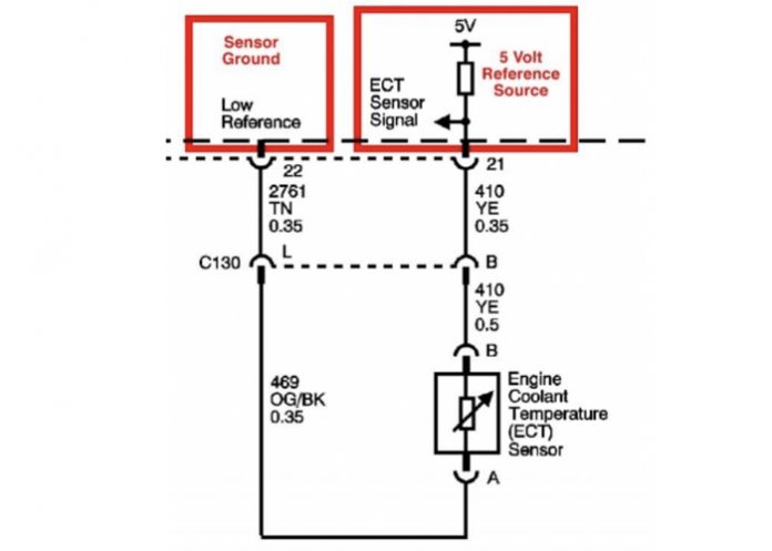
First, look at the circuit (Figure 1). Note the module (ECM in this case), the 5 Volt (5V) reference circuit, the ground (referred to here as “low reference” — some manufacturers call ground “signal return”), and the sensor itself. Just two wires.
Start with the scan tool and navigate to the parameter identification (PID) data for the controlling module. With the ignition key ON and the engine OFF (KOEO), watch the PID data under the following circumstances:
—Sensor disconnected: PID should be about -40˚F/-40˚C.
—Sensor harness wires shorted together with a jumper: PID should be about 280-320˚F/138˚-160˚C.
If you obtain these values on most vehicles, you know the following: the wiring is good, the module that is monitoring the sensor is working (at least on this circuit), and your scan tool is able to relay this information to you.
Now plug the sensor back in and cycle the ignition OFF and back ON. If the temperature PID with the sensor plugged in is not as you expected grab the infrared thermometer and scan the sensor. If the IR thermometer displays a value that makes sense for that operating condition, replace the temperature sensor.
If the PID value sticks at the higher temperature during all phases of testing, your yellow (YE) wire is likely grounded somewhere along its length. Diagnosis now moves to the DVOM and the ECM connector pin for the 5 Volt (5V) reference circuit. It would be acceptable to snip the yellow wire approximately two inches from the ECM connector and measure the ECM end of the cut wire for the presence of the 5V. If you find 5V on the cut end the fault is a short to ground somewhere along the length of the yellow wire. The fix is simple: snip the yellow wire a few inches from the ECT and overlay a new wire on top of the harness in place of the damaged wire.
If your temperature is always -40 degrees, your problem may be an open in the 5V reference yellow wire OR an open in the orange wire with the black stripe (OG/BK) for the low reference circuit (ground). Again, the DVOM is needed to determine if we have 5V at the terminal “B” of the ECT harness connector. If we do, move onto testing of the OG/BK wiring for opens. A simple way to test the OG/BK is to place your black DVOM probe on the terminal “A” of the ECT harness connector and the red DVOM probe on the vehicle’s positive battery terminal. A reading of over 12 volts generally indicates the ground circuit is healthy.
In rare cases a wire will have several broken strands yet will pass resistance testing for continuity. If you doubt the integrity of the wire you will need to perform “loaded wire testing.” You will unplug the wire at both ends, ground one end and use the other end to apply ground to a headlight bulb. A typical sealed high-beam headlight will draw over four AMPS. This is more than adequate to confirm or deny the ability of a typical sensor, data, or actuator wire to perform properly.
Testing a Position Sensor
Drawing on what we learned from testing a two-wire temperature sensor, we can perform testing on three-wire positional sensors. They are often used on throttle bodies, gas pedals, EGR valves, heater blend doors, and even memory power seats.
In this example circuit (Figure 2), the throttle position sensor (TPS) has a 5V reference wire, a sensor ground (which it shares with several other sensors) and a signal wire which typically varies between 0.5V and 4.5V but will never be zero or 5V when operating normally.
Once again, start with the scan tool. With the ignition key ON and the engine OFF (KOEO), look at the PID for the TPS. With the sensor unplugged the TPS voltage should indicate zero. Jumping the Pin 1 orange (OR) 5V Supply (reference) to the Pin 2 orange with dark blue stripe (OR/DB) at the TPS harness connector should result in a PID of 5V. This reading may vary by 0.1 Volt. With that jumper still installed add a second jumper from the Pin 3 black with light blue stripe wire (BK/LB) to the Pin 2. That connection should pull the PID down to zero Volts. These results will confirm that the wiring and the powertrain control module are working properly on this circuit. With these results, issues with trouble codes for this circuit would warrant inspection of the TPS sensor itself for proper installation, adjustment, or failure.
Armed with these hints, you’ll save time and increase your speed and accuracy while diagnosing temperature and position sensing circuits. In an upcoming issue, we will cover testing of exhaust oxygen sensors, pressure sensors, airflow sensors, and speed sensors. •
David Bray is a senior technical writer for ALLDATA.


